Karthik Kadirvel, Design Engineer, Texas Instruments
Over the last few years there has been an increased use of lithium-ion (Li-Ion) batteries in high-power applications such as power tools, yard tools, uninterruptible power supplies (UPS) and hybrid electric vehicles (HEV), which traditionally have been served by nickel metal hydride (NiMH) batteries. Reasons for this trend include higher power density, reduced cost and improved electronics that are needed to manage Li-Ion batteries. In these high-power applications, high voltage and high current is achieved by connecting multiple cells in series and parallel. These high-voltage and high-current Li-Ion battery packs present new challenges for battery management electronics. Traditional single-cell and two-cell Li-Ion battery packs such as those used in cell phones and digital cameras do not face these issues. In this article, key considerations in battery management design for large cell count systems are discussed. These include cell balancing, open sense line detection, communication between the monitoring integrated circuits (ICs) and random cell connection.
In Li-Ion battery packs containing multiple series and parallel connected cells, there exists small differences in cell capacity, cell impedance and state-of-charge between the individual cells. The reasons for these differences include manufacturing tolerances, uneven heating of the different cells in the pack and aging. These small differences manifest themselves as different open circuit voltages for each of the cells in the battery pack. For the battery pack end user, cell voltage imbalance leads to reduced battery capacity per charge-discharge cycle and reduced overall battery lifetime. To address this problem, battery management ICs must include circuitry to balance the individual cells in the battery pack.
Two commonly used algorithms for balancing the cells are voltage balancing and capacity balancing. In voltage balancing, the simpler of the two algorithms, charge is removed from or added to the various cells in the battery pack until the voltages of individual cells match. In capacity-based balancing, the state-of-charge for each cell is measured using various gas gauging techniques. The charge is then removed or added to match the individual cells’ state-of-charge. Two main techniques for implementing these algorithms are passive balancing and active balancing. In passive balancing, a known load, implemented using a resistor and a MOFET switch, is connected across the individual cells to reduce the voltage or capacity to match that of the other cells. The switch and resistor can be internal or external to the IC. TI’s bq77pl910 implements passive bleed balancing using internal switches.[1]

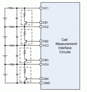
Figure 1 shows a picture of a four-cell system using external resistors and switches to perform passive bleed balancing. In this system, the IC periodically measures the cell voltages. Once the cell voltages are measured, the IC determines the cell with the lowest voltage and turns on the switches across the other cells to reduce their voltage to match the cell with the lowest voltage. The external resistor and the MOSFET ON resistance determine the peak-balancing current. Different average balancing currents can be obtained by using pulse-width modulation (PWM) of the MOSFET gate signal. The main advantage of passive balancing is ease of circuit and algorithm implementation. The main disadvantage of this scheme is that system energy is wasted as heat in the resistor. Furthermore, the heat produced by the bleed resistors can affect cell voltage measurement and potentially can accelerate cell-aging.
In active balancing, the excess capacity in a cell is transferred to a cell with lower capacity using external inductors or capacitors. When external capacitors are used, the principle of operation is similar to that of charge pumps. The excess capacity is first transferred to an external transfer capacitor. Then the capacitor is connected to the cell with lower capacity to transfer the energy. This technique also can be used to balance the voltage as opposed to balancing capacity. When external inductors[2] are used for active balancing, the principle of operation is similar to that of a traditional switching (buck/boost) converter where energy is temporarily stored in the magnetic field of an inductor, then transferred to the cell of interest. The main advantage of active balancing is that the excess capacity (or voltage) in a cell is not wasted as heat. It is efficiently transferred to a cell with lower capacity (or voltage). The main disadvantage of this technique is the increased component count as one inductor and two switches are needed per cell. This leads to a large PCB. Also, switching regulators emit electromagnetic radiation, which can lead to noise issues that corrupt cell-voltage measurement.

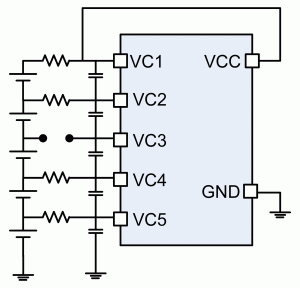
The next common consideration in large cell count systems is the detection of open sense lines. Figure 2 shows a five-cell Li-Ion battery pack being monitored by an IC. A simple RC low-pass filter usually is connected across each cell to reduce noise on the cell voltage measurement input. It is possible that the sense line (consisting of the RC filter) connecting the positive terminal of cells to the IC has increased impedance. For example, in Figure 2, all cells are connected to the IC with a 1 kOhm resistor, except cell three. This increased impedance could be because of bad soldering or poor welding during the manufacturing process, or due to mechanical damage during normal pack operation.
Increased impedance can lead to a hazardous condition as the cell is not monitored anymore and potentially can be over-charged. Therefore, this hazardous condition must be detected and appropriate action taken to prevent damage to the system or user. A common algorithm used to detect open sense lines is for the monitoring IC to periodically apply a known load to each of the individual cells. The load current applied flows through the IC and is measured. If the load current matches a predetermined value based on the correct sense line impedance, then the sense line connection is deemed to be working correctly.
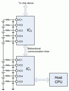
A relatively new application of Li-Ion battery packs is in hybrid electric vehicles. In these applications, thousands of cells[3] are connected in series and parallel configuration to get the high voltage (450 V) and high current needed to operate the automobile. In these systems it is not possible for a single IC to monitor the complete battery pack. In such cases, multiple ICs can be stacked to monitor the cells. The ICs may communicate with each other to transmit information about the cells below or above it. Figure 3 shows a schematic of a 10-cell pack monitored by two ICs, with each IC monitoring five cells. When ICs are stacked, the bottom most IC is referenced to the true system ground while all the ICs above are referenced to the total voltage of the cells below it. In Figure 3, the bottom most IC, IC1, operates between true ground and 20.5 V (=5 by 4.1 V) nominally while the IC above it, IC2, operates between 20.5 V and 41 V.
 The stacking of multiple ICs can be divided into two broad techniques. In the simplest technique, the existing pins of the standalone IC are configured in a special way to transmit the information with or without external components[4]. In the second technique, pins dedicated for stacked communication are used[2]. The main consideration in designing a communication system between ICs operating between different voltage levels is that a level-shifter is needed to translate the information between the different voltage domains. This can be done using voltage-mode signaling using external coupling capacitors, or by using current-mode signaling. The advantage of current-mode signaling is that no external components are needed to perform the communication. One implementation of this technique is TI’s BQ77PL536 IC, which uses current mode signaling between dedicated pins to communicate between the ICs. A custom, noise immune protocol with error correction could be used to improve the communication.
Random cell connection is a phenomenon that occurs during the assembly of the battery pack in the final system. In single-cell and two-cell applications, the assembly process can be designed to guarantee the connection of the battery’s ground (negative) terminal before the positive terminal connection. In systems with a large number of cells in series and parallel, the assembly process cannot guarantee the connection of the ground terminal before the positive terminal. Because of this parasitic diodes inside the IC can be turned on during the assembly process. This could potentially lead to a latch-up condition, which can damage the IC and the battery. Hence, system design must account for random cell connection.
Conclusion
In summary, while designing large cell count systems, additional precautions should be taken because of the matching considerations between cells, assembly challenges and communication challenges associated with communicating between the ICs. In this article some of the key considerations were reviewed along with potential IC solutions.
References
1. “Stand-Alone Multi-Cell Lithium-Ion/Polymer Precision Protectors,” Data Sheet, SLUSA07D, Texas Instruments, November 2011.
2. “3 to 6 Series Cell Lithium-Ion Battery Monitor and Secondary Protection IC for EV and HEV Applications Protectors,” Data Sheet, SLUSA08A, Texas Instruments, July 2011,
3. Gene Berdichevsky, Kurt Kelty, JB Straubel and Erik Toomre, “The Tesla Roadster Battery System,” Tesla Motors, December 19, 2007.
4. Karthik Kadirvel, Robert Taylor and John Carpenter, “Stacked Second Level Overvoltage Protectors,” Battery Power and Technology, June 2009.
Karthik Kadirvel is a mixed-signal design engineer in the nano-power energy harvesting group at Texas Instruments. He holds a Doctoral degree from the University of Florida. Karthik can be reached at ti_karthikkadirvel@list.ti.com.
For more information, please contact Texas Instruments at www.ti.com.
This article was printed in the May/June 2012 issue of Battery Power magazine.


