
Peter Panfil, Vice President, Global Power • Emerson Network Power
One of the most widely discussed issues throughout the world today is the rapidly increasing demand for energy within the computing industry. This is fueling interest in energy efficiency solutions worldwide. Many organizations are looking at their data center’s UPS systems to optimize efficiency while protecting availability and maintaining flexibility to quickly meet growing demands.
This article looks at two steps data centers can take with their power infrastructure to achieve that optimal performance. The combination of these two suggestions, utilizing a high-energy efficiency mode and moving to a reserve bus power system configuration, when done correctly with the appropriate considerations and planning, can help to significantly reduce total costs.
High-Energy Efficiency Mode
Many data center professionals are turning to some form of economization in an effort to increase efficiency. Today’s high-availability, double-conversion UPS systems can achieve efficiency improvements through the use of active eco-mode. This mode of operation accomplishes improved efficiency by powering the bulk of the critical load through the bypass path. When power problems are detected, the UPS automatically switches back to double-conversion mode.
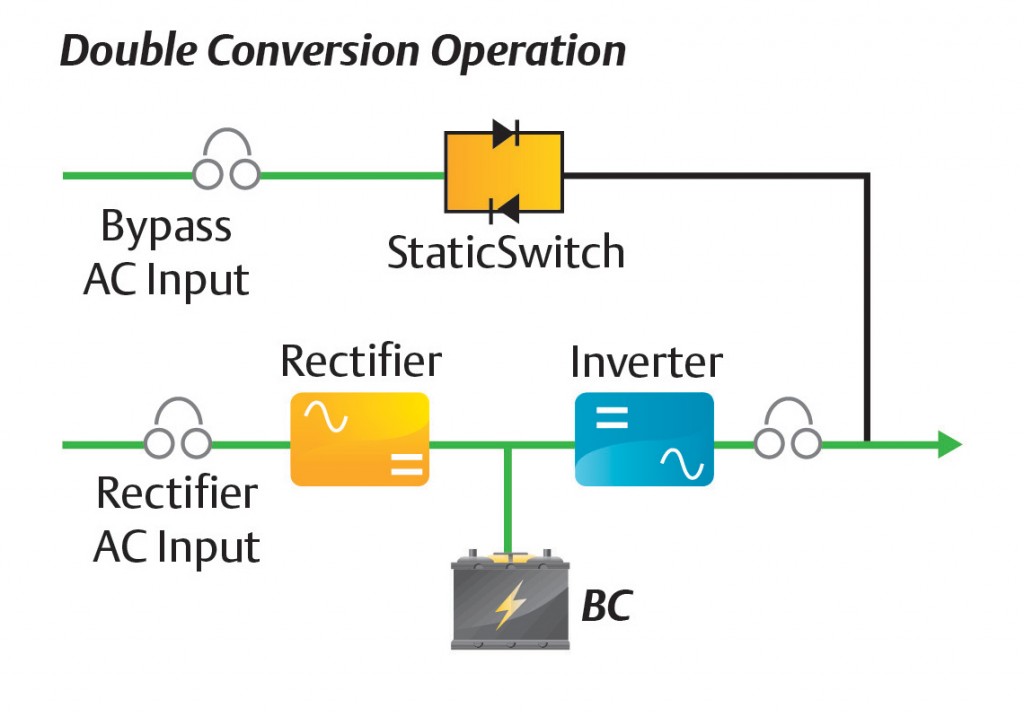
In double-conversion UPS systems (Figure 1), the rectifier and inverter should be designed to run continuously with the rectifier directly powering the inverter. The incoming AC is rectified to DC, which is then converted back to AC by the UPS inverter, resulting in a low-distortion, regulated stable AC output voltage waveform. This process can be up to 97 percent efficient.
Approximately three to six percent of the energy passing through a double-conversion UPS is lost in the conversion process. Traditionally, this has been accepted as a reasonable price to pay for the protection provided by the UPS system.
The active eco-mode approach (Figure 2) pushes efficiency up above 97 percent in some cases. It keeps the inverter and rectifier in an active state, which means the inverter is providing output that matches the bypass and is ready to accept the load immediately.
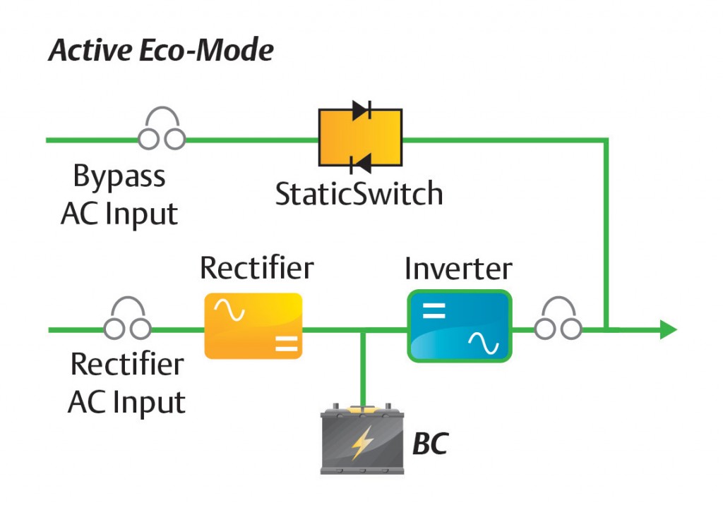
As a result, the transfer to the inverter can be accomplished almost seamlessly. When the UPS senses bypass power quality falling outside accepted levels, the bypass opens and transfers power immediately back to the inverter until bypass anomalies are corrected. Once bypass power anomalies end, the critical load returns to active eco-mode automatically.
It is important to note that not all UPS economization modes are created equal. Due to technology limitations, some UPS systems have to turn off the inverter before turning on the bypass or turn off the bypass before turning on the inverter. This is commonly referred to as an interrupted transfer. In active eco-mode, the UPS controls the inverter to be in a zero power state but keeps the inverter synchronized and ready to take the load. It is due to this technique that going into or suspending active eco-mode operation can be made without any interruption to the load.
Active eco-mode operation is similar to the operation used for transfer. During transfer of the load from bypass to inverter, the inverter matches the bypass voltage and phase angle. The inverter then slightly shifts its phase angle to lead the bypass, effectively moving the load to the inverter. When the static switch is turned off, the load is isolated from the bypass source and the transfer is completed. Active eco-mode operation also connects both the bypass and the inverter simultaneously to the load. The difference is that the inverter matches the bypass voltage and frequency in a manner that allows the inverter to remain
connected to the load.
Reserve Bus Power System
Data centers that demand high availability generally use a dual-bus architecture to eliminate single points of failure across the entire power distribution system. This approach generally includes two independent UPS systems, each capable of carrying the entire load with N capacity after any single failure within the electrical infrastructure. While this is a proven approach for delivering availability, it limits power equipment utilization to under 50 percent, which impacts initial costs and operating costs.
An alternate configuration that has emerged in recent years to support high availability while increasing power equipment utilization is a reserve bus power system. This approach is becoming attractive to organizations seeking near dual-bus availability with lower initial costs, higher equipment utilization, increased scalability and higher efficiency. Reserve architectures also can be designed to enable rapid deployment and modular growth. These benefits have made reserve power systems very attractive to colocated data centers and cloud hosting facilities because they support a business model that depends on providing exceptional customer service at best cost.
While enterprise data centers may operate on a different business model and a smaller scale than many cloud and colocation facilities, they still can benefit from implementing reserve architectures. The benefits aren’t limited to large data centers, and it’s hard to imagine a data center manager who wouldn’t want to achieve efficiency, improved capital costs and great scalability.
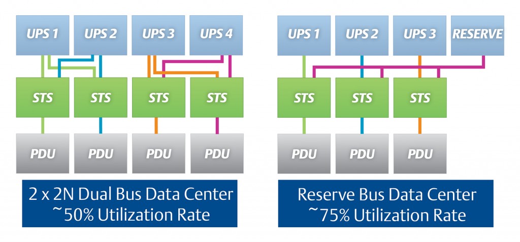
The reserve architecture essentially creates an N+1 or N+ 2 architecture within the AC power system, while maintaining fault tolerance and concurrent maintainability through the use of static transfer switches (STS). The STS allows a redundant (or reserve) UPS system to be brought online to pick up the load in the event of failure or maintenance. Downstream from the STS units, the power distribution system can be similar in design to that of a 2N dual-bus architecture.
Through this arrangement, the reserve architecture allows the UPS system to operate at higher utilization rates, compared to less than 50 percent for a traditional 2N dual bus architecture (Figure 3). Basically, each operating UPS can be loaded up to 100 percent, and a reserve module will “catch” the load if a problem occurs. This means the reserve bus system effectively runs at 75 percent utilization.
Any data center that employs a single bus can deploy a reserve architecture. For example, a Tier 2 data center delivering power via a single bus to a single distribution path is a good candidate for expanding using a reserve architecture.
The key is the use of a downstream STS. The STS uses a primary bus as the main power source and uses the reserve system as its alternate source. If the primary bus goes offline, the STS will transfer power over to the reserve UPS system, and the IT systems will stay on protected power.
Once the reserve architecture is in place, simply adding another IT bus can expand capacity. Most importantly, the performance of the real-time infrastructure being deployed will be significantly improved. First, the power infrastructure can continue to be expanded incrementally without impacting other systems. Second, tying the new capacity to the reserve increases the UPS utilization rate.
Of course, it must be said that any critical power system must be tailored to the organization’s business objectives and specific technology profile as well as the size and criticality of the data center.
Where availability is paramount and UPS modules can be sized to minimize the number of modules in the system, a traditional 2N architecture may still prove to be the right choice. However, for businesses seeking to balance efficiency and availability or where data center capacity makes a 2N architecture unwieldy, the reserve architecture offers a solution that delivers very high reliability with fault tolerance and concurrent maintainability while providing superior efficiency, scalability and resource utilization.
The data center power infrastructure that ensures safe and continuous operation can often represent the least agile and scalable component of the data center. If improperly designed and maintained, it can constrain growth and contribute to downtime. Conversely, the right power infrastructure with the right operating mode can help create a foundation for continuous availability, increased return on capital and cost-effective growth.
 With more than 30 years of experience in embedded controls and power, Peter Panfil leads global market and product development for Emerson Network Power’s Global Power business. He leads the Liebert AC power global roadmap development and is responsible for allocating engineering resources to new product development programs. He also works to apply the latest power and control technology to industry-proven topologies to provide the highest availability systems for business-critical applications. Additionally, Panfil partners with customer groups to incorporate industry trends into new product development. He began his career at Liebert in 1994 and held several managerial positions in engineering before becoming general manager for the AC Power Business.
For more information, visit Emerson Network Power at www.emersonnetworkpower.com.