
Niranjan Pathare, Battery Management Solutions Marketing,
Will Cooper, MSP Microcontroller Product Marketing
Texas Instruments
Today, autonomous sensors are in use for a variety of applications. Typically found in smart buildings and factories, these sensing applications include humidity, temperature, and chemical gas monitoring. They are often placed in remote locations where line power is unavailable, so rely heavily on battery power to function. In order to provide dependable operation, batteries have to be changed often, adding to the total cost of ownership. Ownership cost includes expensive labor needed to change the batteries during routine maintenance.
With the advent of the Internet of Things (IoT) just around the corner, a way to power such small sensors indefinitely is essential. By harvesting ambient energy these autonomous sensors can be powered perpetually without the need to change batteries.
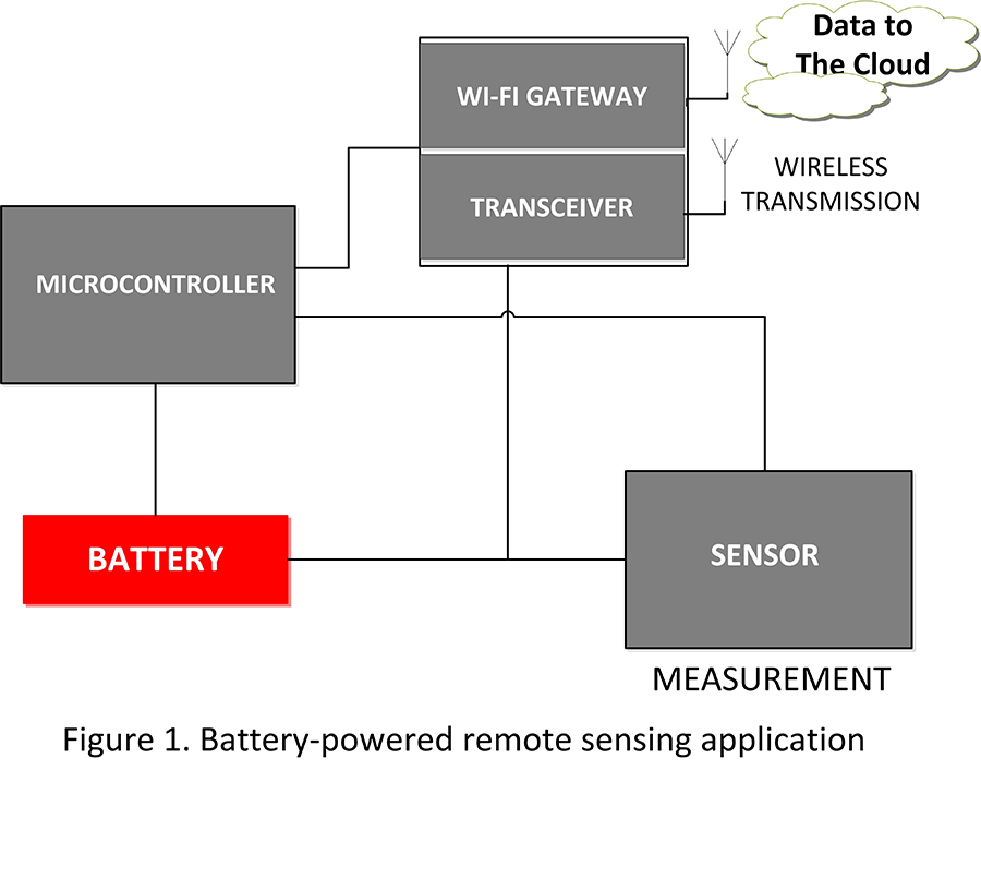
A typical block diagram for a remote sensing application (Figure 1) includes:
1. Energy Source: typically a battery
2. Power Management Devices: monitors and regulates energy from the energy source
3. Sensor: interfaces to the real world and takes measurements
4. Microcontroller: the brain that accepts analog or digital data, processes it, stores the results, and outputs the data to make intelligent decisions
5. Wireless Transceiver: transmits data for further processing by a central unit
In this article, we look at how to replace the limited-life battery with a perpetual power source. In real life, the goal is not to eliminate the battery, but to replace it with a rechargeable storage element. An alternative is to supplement the existing battery to extend the run time of the sensing system. Energy harvesting can help to accomplish this goal. Then we review the requirements of the microcontroller, sensor and transceiver to help you to understand how your design impacts the system’s overall power consumption.
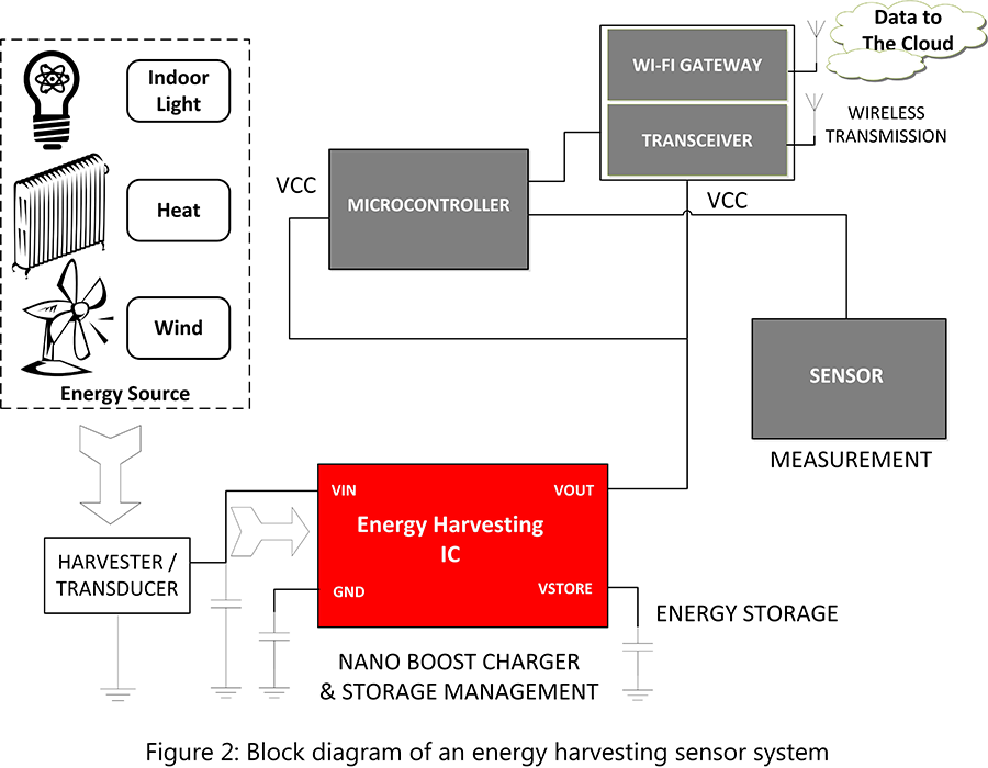
A typical block diagram for an energy-harvesting, remote-sensing application is shown in Figure 2. The battery in Figure 1 is replaced (or possibly augmented) by an ambient energy-harvesting element, an energy-harvesting power management IC and a storage element.
Ambient Energy as a Power Source
For sensors placed in a remote location, it is imperative that the sensor be able to extract energy from its ambient environment so it can power itself without relying on batteries. Examples of commonly available ambient energy sources are light, heat and vibration (motion). In practice, this means tapping into power sensors placed in the immediate vicinity of a well-lit factory floor, a pipe carrying hot liquid or a vibrating motor. The three most common types of harvesters are: photovoltaic (PV) or solar cells, thermos-electric generators and piezo-electric harvesters.
Light
Solar cells convert light energy to a small electrical voltage. The voltage generated per cell is dependent on the brightness of incident light (measured in Lux). This voltage is usually small, ranging from a few to hundreds of millivolts. Several cells can be stacked in series to provide a larger voltage output. Each cell has a maximum current it can provide. In series-connected cells, the maximum current is the same as the maximum current of an individual cell. To achieve a larger current, these cells have to be connected in parallel. The configuration depends on many factors including light levels expected, cell specifications and sensor form factor.
Key features to consider while selecting PV cells:
• Open Circuit Voltage, VOC
• Short Circuit Current, ISC
• Maximum Power the Cell Can Provide, PMAX
• Maximum Voltage, VMAX
• Maximum Current, IMAX
• Current Density of the Cell, JAC
Manufacturers specify these parameters under a standard measurement condition called 1 sun. These values need to be de-rated to match actual use conditions, and usually are significantly lower.
Thermal Energy
Thermo-electric generators (TEG) are current sources that convert heat (temperature-gradient) into electrical energy. Their operation is based on a phenomenon called the Seebeck effect. The voltage generated is proportional to the semiconductor leg pairs used in the construction, and on the temperature difference (DT) between the top and bottom plates. Key features to look for in a TEG are:
• Power Density
• Output Voltage per Watt of Input Power
• Life Time
• Operating Temperature
• Seebeck Coefficient
Of these, the Seebeck coefficient is the most important parameter. It is directly responsible for the level of output voltage per degree of temperature gradient. For example, a TEG we have experience with is the Micropelt TGP-651. It has a Seebeck coefficient of 60 mV/K and yields up to 1.68 V per watt of thermal input.
The matched output power of a TEG depends on the characteristics of the thermal path between the heat source (hot side) and the ambient (cold side). The TEG has a heat sink on the cold side to dissipate heat and create the temperature gradient. The size of the heat sink greatly impacts the TEG’s performance, especially for open circuit voltage’s relative performance and TEG’s matched-power output. A look at the datasheet of the TGP-651 shows that one can expect matched power output of anywhere between approximately 1.3 mW to 1.7 mW at a DT of 50°C, which is not uncommon in factories where hot liquid or gases are flowing through pipes. In our experience, a power output of 1.3 mW is more than sufficient to run a well-designed sensor node.
Vibration Energy
Piezo-electric harvesters convert mechanical vibrations into alternating current (AC) energy. The AC signal can then be rectified to DC and used as a power source. The element is usually mounted in cantilever fashion on the vibrating source. Further, the vibrational natural frequency of the element must be tuned to the vibrational frequency of the source. As with solar cells, series connection increases open-circuit voltage, while a parallel connection increases current output.
Energy Harvester IC and Energy Storage
If the microcontroller is the brain of the system, the energy harvesting integrated circuit (IC) is its heart. This IC extracts the energy from the harvester, conditions it, and stores it for later on-demand use.
The energy harvesting IC needs to be capable of interfacing to a variety of harvesters and be compatible with different storage elements, such as rechargeable Lithium-Ion (Li-ion) batteries, thin-film batteries, supercapacitors and conventional capacitors. It also needs to be capable of providing battery management features such as overvoltage or undervoltage protection, battery OK signal and battery disconnect.
A most desirable feature for any energy harvesting IC is the capability to accept very low levels of input voltages, as low as a few hundred millivolts. Another feature to consider is whether or not it can support maximum power point tracking (MMPT), which allows maximum power extraction under varying input condition (low light or small DT).
While performing its function of extracting energy and storing it, the energy harvester IC must consume as little energy as possible for itself. This is critical if the ambient energy source is weak, which usually is the case. It is preferable to use an energy harvesting IC, which performs all of the aforementioned functions, and still consume only a few hundred nano-amperes while operating.
As mentioned, a rechargeable storage element is needed to store the extracted energy for later on-demand use and to support the sensors energy needs while the ambient energy source is unavailable. One example is turning off lights in an office during non-business hours.
Some typical storage elements are Li-ion batteries, thin-film batteries, supercapacitors and conventional capacitors. All have their own unique advantages and disadvantages. One factor that affects the selection of storage elements is the amount of times it can recharged before it fails. Li-ion batteries, for example, can be charged/discharged only between 300 to 500 cycles. Supercapacitors, on the other hand, can be charged/discharged millions of times.
Another important factor is for the storage elements to be able to self-discharge. Li-ion batteries have a comparatively low self-discharge and are able to hold the charge for a longer time. Supercapacitors, however, have a much higher self-discharge rate and require frequent charge cycles. Charge time is another significant factor. Li-ion batteries have charge times in hours (depending on capacity), while thin-film batteries have charge times in minutes, and supercapacitors have charge times from seconds to minutes, depending on type and value.
Perpetual Power
As stated, there are many small-scale energy sources abundant in our environment. To operate a small sensor system, we need to be clever in how the system is designed to make full use of the ambient energy source and to power the system perpetually.
Sensing Systems
Moore’s Law states that the number of transistors in an integrated circuit doubles every two years. This implies that processing power increases at the same rate. The issue is that battery development is not growing at a matching pace. This issue is amplified further by the need for smaller product form factors. The introduction of newer technologies such as Li-ion batteries are a step towards longer system battery-life. However, power optimizations and the ability to do more with a reduced power budget is critical to enabling acceptable product battery life. Once a reliable and sustainable power source is established, three additional components must be considered to complete the design of a sensing system: sensor, microcontroller and wireless transceiver.
Profiles of Any Microcontroller
Sensors
Choosing the right sensor for a given application is critical to maximize the performance-to-power ratio. Depending on the purpose of the sensor in the connected system, a variety of factors need to be considered. First, there is data collection. In a green house, for instance, sensors may be required to measure anything from room temperature to moisture in the soil. Some temperature sensors are infrared (IR)-based and can measure temperature from a distance, while others such as resistance temperature detectors (RTDs) require direct contact. The type of data collection is determined by the application. In the green house example, a contactless sensor may be required to measure temperature of specific plants, while another sensor could be directly placed in soil to provide moisture-level data.
These sensors send data as a raw analog value, which requires additional system components to take and convert that value to a digital one. Alternatively, these sensors could include on-chip circuitry to immediately convert the signal from analog to digital, minimizing external components. This choice of data output type can have a direct impact on system size, power and cost. In the green house example, sensor size may not be an issue. However, in a home-automation system, consumers want sensor nodes to be as small as possible.
Microcontroller
Choosing the right microcontroller (MCU) for an application is not an easy task. These devices require decisions based on power consumption, memory type, processing performance, size and cost. This type of decision is made even more difficult by the variety of information types available for comparing MCUs. Given the microcontroller is often used as the brain of a sensing system, it can have a big impact on total system power.
One fact to consider when comparing microcontrollers is that power is determined by more than one number. These numbers should include active and standby-mode power consumption (with understanding of the duty-cycle), power required to store data in memory, and power required to run other integrated MCU components. Earlier we discussed using digital or analog sensors and how choosing between the two could be based on performance or power considerations.
In looking at a microcontroller, analog integration can offer advantages in terms of size and power. In the green house example where we need to preserve as much energy as possible, the ability to take in temperature data and store it in memory without waking up the main CPU could be a leading factor in maximizing battery life.
Remember that software can play a major role in your system’s total energy consumption. Floating input/output pins or improper initialization of the MCU can dramatically alter its low-power effectiveness. Optimization tools can be critical in helping developers ensure that once a microcontroller is chosen, it actually delivers the desired results. While this information may not be a new concept, it likely will lead to a fundamental question, “Where should you start?”
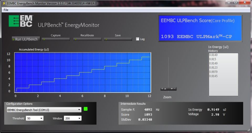
New benchmarks are available to make this part of the decision a little simpler. For example, the ULPBench benchmark, from the Embedded Microprocessor Benchmark Consortium (EEMBC), considers key low-power system functions that include use of low-power modes and a real-time clock (RTC). Perhaps even more useful, is the ULPBench EnergyMonitor tool that can be used to run the benchmark and directly measure power consumption of your application, on any microcontroller in the industry.
Beyond power, other considerations are important in choosing a microcontroller. Memory technology can play a leading role in the performance of a system sensor. Choosing the right memory requirements for a microcontroller can be based on requirements for total storage, speed and power. Using RAM to execute the system stack offers advantages in terms of power and speed over Flash for many years. EEPROM can extend the MCU’s memory footprint and offer higher endurance in datalogging scenarios.
What if a better solution existed? One that provides the benefits of non-volatile memory with the speed and ease-of-writing associated with RAM? Enter ferroelectric random access memory (FRAM). This non-volatile RAM technology can offer the best of both worlds with 1,015 write cycle endurance, ultra-fast write speeds, and ultra-low-power writes. This means that in the green house, you can record millions of data-points over the systems lifetime instead of thousands, enabling smarter decisions. The negative is cost when it comes to larger memory footprints, but this can be overcome in applications where information is collected and then transmitted to the cloud for centralized storage and analysis of system data.
Wireless Transceiver
Choosing the right wireless transceiver is also key to creating an efficient sensor solution. Even more important is recognizing the relationship between the wireless transceiver and the microcontroller in a system. Choices about whether or not a full system-on-chip (SOC) solution is preferred over a two-chip solution can have impacts on size, power and software. From the software perspective, developers may prefer a fully integrated stack, built into the radio, or to create or optimize the stack themselves within the application code on the MCU.
What’s more, depending on the environment, a sensor may need to share data with a hub via Wi-Fi, Bluetooth, Mesh networking, or even sub-1GHz communication. These wireless topologies all offer their own advantages in terms of range, power-consumption and usability by consumers. While Wi-Fi is not the most power-efficient solution, it can offer great range in a home environment and can connect directly with the common routers found in households. Other sensors may leverage Bluetooth low energy (BLE) for connecting to a phone for use as a central hub. In the green house example, it may make sense to leverage a sub-1 GHz transceiver due to its low transmission power. This requires a gateway to collect information from a variety of sensors to communicate with the cloud.
If the previous paragraph wasn’t clear enough, the cloud is a growing and important part of today’s sensor solutions that make up the IoT. Regardless of protocol used (HTTP, MQTT and so on), the ability of sensor nodes to offload data to a central hub for intensive processing and extended data storage is a huge leap forward in terms of increasing the value of sensor-based systems. There is still space for microcontrollers to help minimize wireless transmission by manipulating data on-chip, but the ability to choose what makes sense for the given application is quite compelling.
Real-World Demo of an Energy Harvesting Sensor System
By combining the above-mentioned system components, we can build a complete energy-harvesting sensor network. The sensor network leverages ambient light, wind, and thermal energy to power the system, which then collects various sensor data (ranging from moisture in a potted plant to ambient light).
Conclusion
This system provides one potential implementation of a practical perpetually-powered system. Depending on the application, the five system components discussed can be adjusted to meet an entirely different set of requirements. To start developing your own wireless sensor node, TI Designs provide full energy-harvesting solutions with complete documentation. With these solutions the proliferation of the IoT, is one step closer.
For questions about this article, Niranjan and William can be reached at ti_niranjanpathare@list.ti.com.