
John C. Copeland, VP/COO, Energy Assurance LLC
From my days as a young Marine Corps Officer, it was stressed that “Safety is Paramount”. The same is very much the case when it comes to the design of small-format secondary lithium battery packs. Failure in this regard risks personal injury and property damage, not to mention significant losses associated with negative publicity for those deemed responsible in the court of public opinion. Ensuring a baseline of safety is managed through robust cell designs, proper design verification, system level risk assessments, and subsequent independent regulatory-compliance actions by third-party test labs to objective test standards. That said, all test standards and their component tests are not the same. The actions and efforts necessary to achieve compliance vary dramatically. Here we will offer a view from inside the test lab to provide a framework of risk assessment, not of the designs themselves, but rather of the relative difficulty of successfully demonstrating test standard compliance.
The approach that follows will begin with a quick discussion of prominent battery pack standards. We’re not attempting to cover all of them, but rather focus on those that make up the majority of our test volume. Peeling the onion, we’ll look at the individual component tests, both their primary specifications as well as the problems seen with achieving compliance. This will be translated into a “stop-light” coding tied to relative difficulty of passing the requirements (Red-High Risk; Yellow-Medium Risk; Green-Low Risk). Wrapping up, we’ll cover some general ideas on mitigation to improve the odds of first time success.
For small format rechargeable lithium battery applications, there are three standards that enjoy the widest usage for consumer and commercial applications.
IEC 62133
IEC 62133:2012 (2nd Edition) – Rechargeable cell/battery safety: This is the de facto standard for international compliance. Mandated by many IEC end-device standards, it has also served as the basis for many country-specific battery test standards. It offers both mechanical and non-faulted electrical tests with charging preparation done at temperature extremes. Note that compliance to UN 38.3 transportation testing is an integral requirement.
The actual test list for secondary battery packs was dramatically reduced with the release of the second edition of IEC 62133. This was primarily due to the removal of all tests that were included within the scope of UN 38.3 testing (compliance to UN requirements must be provided, but the testing does not have to be repeated). This leaves only four actual tests: Moulded Case Stress, External Short Circuit, Free Fall and Overcharging of Battery.
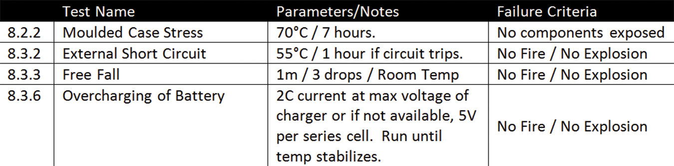
Mechanically, the moulded case stress test is run at a temperature just above the typical electrical operating range of most battery packs and well within most plastic specs used for such applications. The drop test is 1 meter to concrete and does not involve any cold temperature pre-conditioning regardless of the specified lower operating temp for the battery. Electrically, the testing is run on un-faulted samples, so this regime is truly a test of the safety circuit as-is. If there is sufficient design margin to over-voltage and the safety 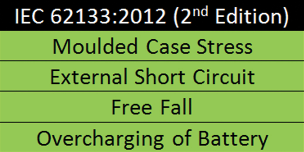 circuit promptly shuts off when a short is detected, the risk of event is small.
Summarizing, if a pack design incorporates reasonable robustness to limited mechanical and electrical stress, the overall risk of non-compliance to IEC 62133 2nd Edition is relatively low.
UN 38.3
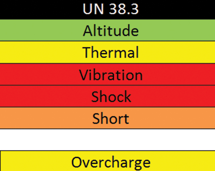
UN 38.3 – Recommendations on the Transport of Dangerous Goods; Manual of Test and Criteria, Fifth revised edition, Amendment 1: Want to ship a lithium battery almost anywhere in the world by air, vessel, rail or truck? Plan on complying with this test standard. It is commonly known as “T1-T8” testing based on the test reference numbers and sequence. Found in many countries’ shipment of dangerous goods regulations, it presents a combination of significant environmental, mechanical, and electrical stresses, in many cases well above typical lithium battery specifications.
Although the UN test profile does not involve any faulting, it does add the dimension of sequential stresses. This is where the same group of samples is put through a series of tests (tests T.1 through T.5). For packs, the testing is two-prong.
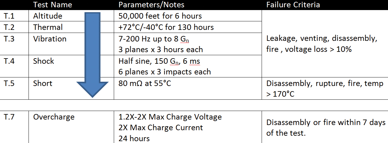
The altitude test is generally innocuous. In over a decade of testing, we’ve only seen one product fail. The same cannot be said for the other tests. Thermal testing is conducted above the limit of most lithium ion cells. In addition to aging the cells, it also induces thermal fatigue potentially weakening connections. Vibration is intense. I tell our clients that their battery will experience vibration above that expected of many military grade products. Not only is the profile itself stressful, but it is run for a full three hours in each of the three cardinal planes. Shock is also quite significant with six times the number of impacts used by other similar standards. Finishing up the regime, short circuit is conducted outside the thermal operating range of most packs. For the T1-T5 sequence, although the individual tests are tough, it’s the cumulative effect that is the concern. The combination of thermal, vibration and shock represent a very honest attempt to damage the pack. Assuming the pack survives that beating, it is then short circuited at high temperature to ensure that the cells are still protected. Again, this is a very mechanically intense profile.
 Overcharge is run on a separate group of samples and is designed to simulate a pack being improperly charged for an extended duration and then presented for shipment where it sits in channel for a week. For a successful outcome, the safety circuit must function properly. Pitfalls are if the circuit does not fully shut off (allows a small current to flow) or oscillates off and on to a point where overcharging still occurs. In our experience, the failures generally occur during the charging phase, not during the seven-day wait period.
Summarizing the risk by test, vibration and shock represent the most significant source of test non-compliances due to their intensity and the effects of cumulative stress. Thermal is included as a medium concern as it sometimes induces failures itself, or contributes to the failures that occur during vibration or shock. Short circuit being a final check of extended safety circuit performance is in a special category. Although we don’t see as many failures in short, the fact that it is a final evaluation warrants concern to ensure electrical functionality after stress. Finally overcharge performance is also a medium risk tied to safety circuit robustness to the combination of high voltage and high current.
UL 2054
UL 2054 – Household and Commercial Batteries, Second Edition: Compliance to this standard is mandated by a number of US end device standards. By all accounts, it is a difficult standard involving roughly double the number of tests found in the UN or IEC requirements. Most notable, UL 2054 introduces single faults of the electrical circuit into the scope. Compounding this affect, it also requires operation just below the trip point of the faulted circuit to attain independent certification, thus simulating a true worst-case scenario.
Before looking into the individual test requirements, a discussion on faulting is in order. Exactly what faults will be applied to the battery packs prior to stress? Listed next are four common faults employed in the majority of projects we see:
• The source and drain of the charge or discharge FET are
shorted together by means of a wire jumper.
• The charge or discharge FET gate is tied to either Cell+ or
Cell- to prevent the FET from stopping the flow of current.
• The sense resistor is shorted.
• The FET control output of the safety IC (charge and
discharge) are shorted together.
Note: If the components are either too small to fault or are otherwise inaccessible, the standard practice is to fault out the entire board.
Again, only a single fault is applied to a given device. Multiple faults are never specified, although it is very possible that the combination of a single fault and the applied stress may result in a cascading failure that impacts other components on the board and their associated functionality.
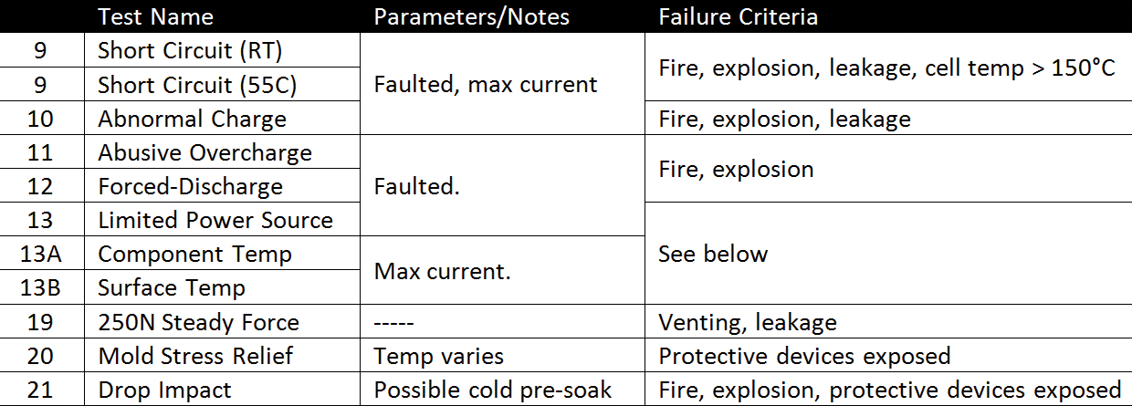
Looking at the individual electrical tests, short circuit, abnormal charge and component & surface temp are run at the experimentally determined maximum no-trip current for each fault mode. Abnormal charge is a high current test where the maximum charge voltage is not exceeded. Abusive overcharge is an overvoltage test where the current is high but limited. Specifically the test is run at a minimum of 6 V per series cell. As lithium ion devices are very sensitive to overvoltage, this is a particularly difficult test where failures are not uncommon. Forced discharge is run only on series connected cells (two in series or higher). All but one series cell is fully charged. The remaining cell is fully discharged. The pack is then hard shorted resulting in significant electrical stress on the fully discharged cell. For a pack to be classified as a limited power source, it must deliver <8 amps and <100 watts after a specified duration of time (the duration is based on the pack’s design). Note that there are a multitude of test cases for limited power source. The two noted above are the most common.
The Component Temperature test ensures that the thermal specifications of critical components are not exceeded when the battery is operated at its maximum ambient temperature and highest current. The surface temperature test is typically run at the same time and ensures that the outside surface of the battery does not present a touch hazard to the user.
Mechanical testing introduces a few new aspects. If a pack’s minimum rated ambient temperature is less than 0°C, then the pack must be soaked for 3 hours at that temperature immediately before drop testing. In most cases, this leaves the plastic at its most brittle state. Mold stress relief is not run at a fixed temperature, but rather one derived from the component temperature test. In practices, test temperatures greater than 90°C are not uncommon. The 250N steady force test involves applying a force of 250N via a 30 mm diameter metal disk on all sides of the product.
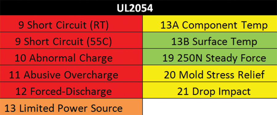 The relative risk by test in this regime is highly focused on the electrical tests. With the inclusion of single faults and worst-case operation, these tests require extra attention during the design process to ensure a positive outcome. By far, the abusive overcharge test is the most significant given the overvoltage conditions applied to the faulted pack. Two levels of protection against overvoltage are suggested as one will be removed via faulting. Abnormal charge, forced discharge and both short circuit tests also involve significant test risk due to faulting and worst case operation. A key to success is knowing in advance how the design will behave under these conditions and how much margin is available. The limited power source test represents challenges for bigger packs. If the pack’s normal voltage and current put it close to the limit for LPS compliance, the addition of faults will only reduce the available margin. Knowing this up front and communicating this to the end device manufacturer is important (this means that some of the pack’s requirements may have to be accounted for in the end device). Mechanically, mold stress (due to its potentially high temps), drop (due to possible brittleness from cold temperature soaking), and component temp (due to component thermal limits) involve medium risk. Surface temp and 250N steady force are generally benign for minimally robust designs.
Summary
Today’s modern battery test standards and their component tests run the gambit from relatively benign to significantly difficult. Knowing the relative risk of each test can help with the allocation of limited resources during the design phase to maximize the chance of a successful regulatory outcome. An outline for compliance should include:
• Understand early what test standards will be applicable to your product.
• Evaluate each component test by relative risk to help allocate engineering resources.
• Thoroughly investigate the product’s behavior at the expected test conditions. Include the aspects of serial testing, faulting, preconditioning (aging, etc.), and worst-case operation if applicable.
• Develop and implement mitigation strategies for the design.
• Consider independent pre-testing early in the design process to reduce future schedule risk.
• Talk to your regulatory test provider early. They are an extra set of skilled eyes with a wealth of knowledge about testing and the associated regulatory environment.
For more information, please visit www.energy-assurance.com.